

Introduction
This is comprehensive tutorial on inverse kinematics for Arduino robots addresses one of the most challenging aspects of robotics programming: creating smooth, coordinated movement without manually programming each servo. With custom hexapod robot as a practical example, inside video transforms complex mathematical concepts into accessible, implementable code that any Arduino enthusiast can understand and apply. The Complete Implementation Guide are as follow:
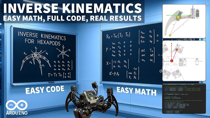
Master Inverse Kinematics for Arduino Robots – Complete Implementation Guide
Table of Contents
- Overview
- Hardware Requirements
- Software Installation
- Mathematical Foundation
- Source Code Implementation
- Hardware Setup and Configuration
- Test Programs
- Troubleshooting
- Advanced Features
Overview
This guide provides a complete implementation of inverse kinematics for Arduino-based robots, specifically designed for hexapod walking robots but adaptable to any multi-joint robotic system. The implementation uses simple trigonometry and object-oriented programming to achieve smooth, coordinated movement.
Hardware Requirements
Essential Components
- Arduino Uno/Mega (Mega recommended for multiple servos)
- 18x Servo Motors (SG90 or similar for hexapod)
- PCA9685 16-Channel PWM Driver (or similar servo controller)
- 6V Power Supply (sufficient amperage for all servos)
- Breadboard and Jumper Wires
- Robot Frame (custom or commercial hexapod frame)
Optional Components
- HC-05 Bluetooth Module (for wireless control)
- Ultrasonic Sensor (for obstacle avoidance)
- IMU Module (for balance control)
Software Installation
Arduino IDE Setup
- Install Arduino IDE
Download from: <https://www.arduino.cc/en/software> - Install Required Libraries
Tools -> Manage Libraries -> Search and Install: - Adafruit PWM Servo Driver Library - Wire Library (usually pre-installed) - Board Configuration
Tools -> Board -> Arduino Uno/Mega Tools -> Port -> [Select appropriate COM port]
Mathematical Foundation
Coordinate System
- X-axis: Forward direction
- Y-axis: Left direction (when viewed from back)
- Z-axis: Upward direction
- Angles: All calculations in degrees for simplicity
Core Mathematical Functions
// Degree to Radian conversion
#define DEG_TO_RAD(x) ((x) * PI / 180.0)
#define RAD_TO_DEG(x) ((x) * 180.0 / PI)

// Essential trigonometric calculations
float calculateAngle(float x, float y) {
    return RAD_TO_DEG(atan2(y, x));
}

float calculateDistance(float x, float y) {
    return sqrt(x*x + y*y);
}

float lawOfCosines(float a, float b, float c) {
    return RAD_TO_DEG(acos((a*a + b*b - c*c) / (2*a*b)));
}
Source Code Implementation
1. Servo Class
// Servo.h
#ifndef SERVO_H
#define SERVO_H

#include <Adafruit_PWMServoDriver.h>

class RobotServo {
private:
    int channel;
    bool reversed;
    int minPulse;
    int maxPulse;
    float currentAngle;
    Adafruit_PWMServoDriver* pwm;

public:
    RobotServo(Adafruit_PWMServoDriver* pwmDriver, int ch, bool rev = false);
    void setAngle(float angle);
    void setSpeed(int speed);
    float getCurrentAngle();
    void initialize();
};

#endif

// Servo.cpp
#include "Servo.h"

RobotServo::RobotServo(Adafruit_PWMServoDriver* pwmDriver, int ch, bool rev) {
    pwm = pwmDriver;
    channel = ch;
    reversed = rev;
    minPulse = 150;  // Minimum pulse width
    maxPulse = 650;  // Maximum pulse width
    currentAngle = 0;
}

void RobotServo::setAngle(float angle) {
    // Constrain angle to -90 to +90 degrees
    angle = constrain(angle, -90, 90);

    if (reversed) {
        angle = -angle;
    }

    // Convert angle to pulse width
    int pulse = map(angle + 90, 0, 180, minPulse, maxPulse);
    pwm->setPWM(channel, 0, pulse);
    currentAngle = angle;
}

void RobotServo::initialize() {
    setAngle(0);  // Set to center position
}

float RobotServo::getCurrentAngle() {
    return currentAngle;
}
2. Leg Class
// Leg.h
#ifndef LEG_H
#define LEG_H

#include "Servo.h"

struct Point3D {
    float x, y, z;
    Point3D(float x = 0, float y = 0, float z = 0) : x(x), y(y), z(z) {}
};

class RobotLeg {
private:
    RobotServo hipServo;
    RobotServo kneeServo;
    RobotServo footServo;

    // Physical dimensions (in mm)
    float thighLength;
    float footLength;
    float gapAngle;

    // Leg configuration
    Point3D anchorPosition;
    float initialRotation;
    Point3D kneeOffset;

    // Helper functions
    float calculateHipAngle(Point3D footPos);
    float calculateKneeAngle(float y, float z);
    float calculateFootAngle(float y, float z);
    Point3D rotatePoint(Point3D point, float angle);

public:
    RobotLeg(Adafruit_PWMServoDriver* pwm, int hipCh, int kneeCh, int footCh,
             Point3D anchor, float rotation, bool hipRev = false,
             bool kneeRev = false, bool footRev = false);

    void setFootPosition(Point3D position);
    void initialize();
    void setDimensions(float thigh, float foot, float gap);
};

#endif

// Leg.cpp
#include "Leg.h"
#include <math.h>

RobotLeg::RobotLeg(Adafruit_PWMServoDriver* pwm, int hipCh, int kneeCh, int footCh,
                   Point3D anchor, float rotation, bool hipRev, bool kneeRev, bool footRev)
    : hipServo(pwm, hipCh, hipRev),
      kneeServo(pwm, kneeCh, kneeRev),
      footServo(pwm, footCh, footRev),
      anchorPosition(anchor),
      initialRotation(rotation) {

    // Default dimensions (adjust for your robot)
    thighLength = 84.0;   // mm
    footLength = 127.0;   // mm
    gapAngle = 14.0;      // degrees
    kneeOffset = Point3D(0, 20, 0);  // mm
}

void RobotLeg::setDimensions(float thigh, float foot, float gap) {
    thighLength = thigh;
    footLength = foot;
    gapAngle = gap;
}

void RobotLeg::setFootPosition(Point3D position) {
    // Convert position from robot center to leg anchor
    Point3D relativePos;
    relativePos.x = position.x - anchorPosition.x;
    relativePos.y = position.y - anchorPosition.y;
    relativePos.z = position.z - anchorPosition.z;

    // Calculate hip rotation
    float hipAngle = calculateHipAngle(relativePos);

    // Calculate knee position after hip rotation
    Point3D kneePos = rotatePoint(kneeOffset, hipAngle + initialRotation);

    // Calculate foot position relative to knee
    Point3D footRelativeToKnee;
    footRelativeToKnee.y = relativePos.y - kneePos.y;
    footRelativeToKnee.z = relativePos.z - kneePos.z;

    // Calculate knee and foot angles
    float kneeAngle = calculateKneeAngle(footRelativeToKnee.y, footRelativeToKnee.z);
    float footAngle = calculateFootAngle(footRelativeToKnee.y, footRelativeToKnee.z);

    // Apply angles to servos
    hipServo.setAngle(hipAngle);
    kneeServo.setAngle(kneeAngle);
    footServo.setAngle(footAngle);
}

float RobotLeg::calculateHipAngle(Point3D footPos) {
    float angle = RAD_TO_DEG(atan2(footPos.y, footPos.x));
    return angle - initialRotation;
}

float RobotLeg::calculateKneeAngle(float y, float z) {
    float L = sqrt(y*y + z*z);

    if (L > (thighLength + footLength)) {
        L = thighLength + footLength;  // Constrain to reachable distance
    }

    // Calculate angles using law of cosines
    float angleB = RAD_TO_DEG(acos((thighLength*thighLength + L*L - footLength*footLength) /
                                   (2 * thighLength * L)));
    float angleA = RAD_TO_DEG(atan2(z, y));

    return angleB - angleA;
}

float RobotLeg::calculateFootAngle(float y, float z) {
    float L = sqrt(y*y + z*z);

    if (L > (thighLength + footLength)) {
        L = thighLength + footLength;
    }

    float footAngle = RAD_TO_DEG(acos((footLength*footLength + L*L - thighLength*thighLength) /
                                      (2 * footLength * L)));

    return footAngle - gapAngle;
}

Point3D RobotLeg::rotatePoint(Point3D point, float angle) {
    float rad = DEG_TO_RAD(angle);
    Point3D rotated;
    rotated.x = point.x * cos(rad) - point.y * sin(rad);
    rotated.y = point.x * sin(rad) + point.y * cos(rad);
    rotated.z = point.z;
    return rotated;
}

void RobotLeg::initialize() {
    hipServo.initialize();
    kneeServo.initialize();
    footServo.initialize();
}
3. Hexapod Main Class
// Hexapod.h
#ifndef HEXAPOD_H
#define HEXAPOD_H

#include "Leg.h"
#include <Adafruit_PWMServoDriver.h>

class Hexapod {
private:
    Adafruit_PWMServoDriver pwm;
    RobotLeg* legs[6];

    // Walking parameters
    float stepHeight;
    float stepLength;
    float bodyHeight;
    int currentGait;

public:
    Hexapod();
    void initialize();
    void setStandingPosition();
    void walkForward();
    void walkBackward();
    void turnLeft();
    void turnRight();
    void setBodyHeight(float height);
    void executeGait(int gaitType);
};

#endif

// Hexapod.cpp
#include "Hexapod.h"

Hexapod::Hexapod() : pwm(Adafruit_PWMServoDriver()) {
    stepHeight = 30;   // mm
    stepLength = 40;   // mm
    bodyHeight = -80;  // mm (negative = below knee level)
    currentGait = 0;
}

void Hexapod::initialize() {
    pwm.begin();
    pwm.setPWMFreq(60);  // Analog servos run at ~60 Hz

    // Initialize legs with their anchor positions and initial rotations
    legs[0] = new RobotLeg(&pwm, 0, 1, 2, Point3D(60, -104, 0), 45);   // Right Front
    legs[1] = new RobotLeg(&pwm, 3, 4, 5, Point3D(0, -120, 0), 90);    // Right Middle
    legs[2] = new RobotLeg(&pwm, 6, 7, 8, Point3D(-60, -104, 0), 135); // Right Rear
    legs[3] = new RobotLeg(&pwm, 9, 10, 11, Point3D(-60, 104, 0), 225, true, true, true); // Left Rear
    legs[4] = new RobotLeg(&pwm, 12, 13, 14, Point3D(0, 120, 0), 270, true, true, true);  // Left Middle
    legs[5] = new RobotLeg(&pwm, 15, 16, 17, Point3D(60, 104, 0), 315, true, true, true); // Left Front

    // Initialize all legs
    for (int i = 0; i < 6; i++) {
        legs[i]->initialize();
    }

    delay(1000);
    setStandingPosition();
}

void Hexapod::setStandingPosition() {
    Point3D standingPositions[6] = {
        Point3D(120, -80, bodyHeight),   // Right Front
        Point3D(80, -120, bodyHeight),   // Right Middle
        Point3D(40, -80, bodyHeight),    // Right Rear
        Point3D(40, 80, bodyHeight),     // Left Rear
        Point3D(80, 120, bodyHeight),    // Left Middle
        Point3D(120, 80, bodyHeight)     // Left Front
    };

    for (int i = 0; i < 6; i++) {
        legs[i]->setFootPosition(standingPositions[i]);
    }
    delay(500);
}

void Hexapod::walkForward() {
    // Tripod gait - legs move in two groups
    Point3D positions[6];

    // Step 1: Lift right front, left middle, right rear
    for (int step = 0; step < 2; step++) {
        int liftGroup[3] = {0, 4, 2};  // Legs to lift
        int groundGroup[3] = {1, 3, 5}; // Legs on ground

        if (step == 1) {
            liftGroup[0] = 1; liftGroup[1] = 3; liftGroup[2] = 5;
            groundGroup[0] = 0; groundGroup[1] = 4; groundGroup[2] = 2;
        }

        // Lift phase
        for (int i = 0; i < 3; i++) {
            int legIndex = liftGroup[i];
            Point3D currentPos = getCurrentFootPosition(legIndex);
            currentPos.z = bodyHeight + stepHeight;
            currentPos.x += stepLength;
            legs[legIndex]->setFootPosition(currentPos);
        }
        delay(200);

        // Lower phase
        for (int i = 0; i < 3; i++) {
            int legIndex = liftGroup[i];
            Point3D currentPos = getCurrentFootPosition(legIndex);
            currentPos.z = bodyHeight;
            legs[legIndex]->setFootPosition(currentPos);
        }
        delay(200);

        // Push back with ground legs
        for (int i = 0; i < 3; i++) {
            int legIndex = groundGroup[i];
            Point3D currentPos = getCurrentFootPosition(legIndex);
            currentPos.x -= stepLength;
            legs[legIndex]->setFootPosition(currentPos);
        }
        delay(200);
    }
}

Point3D Hexapod::getCurrentFootPosition(int legIndex) {
    // This would typically track current positions
    // For simplicity, return default standing position
    Point3D standingPositions[6] = {
        Point3D(120, -80, bodyHeight),
        Point3D(80, -120, bodyHeight),
        Point3D(40, -80, bodyHeight),
        Point3D(40, 80, bodyHeight),
        Point3D(80, 120, bodyHeight),
        Point3D(120, 80, bodyHeight)
    };
    return standingPositions[legIndex];
}

void Hexapod::setBodyHeight(float height) {
    bodyHeight = height;
    setStandingPosition();
}
Hardware Setup and Configuration
1. Servo Controller Wiring
PCA9685 Connections:
VCC  -> 5V (Arduino)
GND  -> GND (Arduino)
SDA  -> A4 (Arduino Uno) / Pin 20 (Arduino Mega)
SCL  -> A5 (Arduino Uno) / Pin 21 (Arduino Mega)
V+   -> 6V External Power Supply (+)
GND  -> 6V External Power Supply (-) + Arduino GND
2. Servo Channel Assignment
// Channel mapping for hexapod legs
// Right Front Leg:  Channels 0-2  (Hip, Knee, Foot)
// Right Middle Leg: Channels 3-5  (Hip, Knee, Foot)
// Right Rear Leg:   Channels 6-8  (Hip, Knee, Foot)
// Left Rear Leg:    Channels 9-11 (Hip, Knee, Foot)
// Left Middle Leg:  Channels 12-14 (Hip, Knee, Foot)
// Left Front Leg:   Channels 15-17 (Hip, Knee, Foot)
3. Physical Measurements
Measure your robot’s dimensions and update these values:
// In your setup() function:
for (int i = 0; i < 6; i++) {
    legs[i]->setDimensions(
        84.0,  // Thigh length (mm)
        127.0, // Foot length (mm)
        14.0   // Gap angle (degrees)
    );
}
Test Programs
1. Basic Servo Test
// ServoTest.ino
#include <Adafruit_PWMServoDriver.h>

Adafruit_PWMServoDriver pwm = Adafruit_PWMServoDriver();

void setup() {
    Serial.begin(9600);
    pwm.begin();
    pwm.setPWMFreq(60);
    Serial.println("Servo Test Starting...");
}

void loop() {
    // Test all servos one by one
    for (int channel = 0; channel < 18; channel++) {
        Serial.print("Testing servo on channel: ");
        Serial.println(channel);

        // Move to center
        pwm.setPWM(channel, 0, 400);
        delay(1000);

        // Move to one extreme
        pwm.setPWM(channel, 0, 150);
        delay(1000);

        // Move to other extreme
        pwm.setPWM(channel, 0, 650);
        delay(1000);

        // Return to center
        pwm.setPWM(channel, 0, 400);
        delay(1000);
    }
}
2. Single Leg Test
// SingleLegTest.ino
#include "Leg.h"
#include <Adafruit_PWMServoDriver.h>

Adafruit_PWMServoDriver pwm;
RobotLeg* testLeg;

void setup() {
    Serial.begin(9600);
    pwm.begin();
    pwm.setPWMFreq(60);

    // Create a test leg (Right Front)
    testLeg = new RobotLeg(&pwm, 0, 1, 2, Point3D(60, -104, 0), 45);
    testLeg->initialize();

    Serial.println("Single Leg Test Starting...");
    delay(2000);
}

void loop() {
    Serial.println("Moving to standing position...");
    testLeg->setFootPosition(Point3D(120, -80, -80));
    delay(2000);

    Serial.println("Lifting foot...");
    testLeg->setFootPosition(Point3D(120, -80, -50));
    delay(2000);

    Serial.println("Moving forward...");
    testLeg->setFootPosition(Point3D(140, -80, -50));
    delay(2000);

    Serial.println("Lowering foot...");
    testLeg->setFootPosition(Point3D(140, -80, -80));
    delay(2000);

    Serial.println("Returning to start...");
    testLeg->setFootPosition(Point3D(120, -80, -80));
    delay(2000);
}
3. Full Hexapod Test
// HexapodTest.ino
#include "Hexapod.h"

Hexapod robot;

void setup() {
    Serial.begin(9600);
    Serial.println("Hexapod Test Starting...");

    robot.initialize();
    Serial.println("Robot initialized!");
    delay(2000);
}

void loop() {
    Serial.println("Standing position...");
    robot.setStandingPosition();
    delay(3000);

    Serial.println("Walking forward...");
    for (int i = 0; i < 3; i++) {
        robot.walkForward();
        delay(500);
    }

    Serial.println("Height adjustment test...");
    robot.setBodyHeight(-60);  // Higher
    delay(2000);
    robot.setBodyHeight(-100); // Lower
    delay(2000);
    robot.setBodyHeight(-80);  // Normal
    delay(2000);

    delay(5000);
}
4. Bluetooth Control Test
// BluetoothControl.ino
#include "Hexapod.h"
#include <SoftwareSerial.h>

Hexapod robot;
SoftwareSerial bluetooth(2, 3); // RX, TX

void setup() {
    Serial.begin(9600);
    bluetooth.begin(9600);

    robot.initialize();
    Serial.println("Bluetooth control ready!");
}

void loop() {
    if (bluetooth.available()) {
        char command = bluetooth.read();

        switch (command) {
            case 'F': // Forward
                robot.walkForward();
                break;
            case 'B': // Backward
                robot.walkBackward();
                break;
            case 'L': // Left
                robot.turnLeft();
                break;
            case 'R': // Right
                robot.turnRight();
                break;
            case 'S': // Stop/Stand
                robot.setStandingPosition();
                break;
            case 'U': // Up
                robot.setBodyHeight(-60);
                break;
            case 'D': // Down
                robot.setBodyHeight(-100);
                break;
            default:
                robot.setStandingPosition();
                break;
        }
    }
}
Troubleshooting
Common Issues and Solutions
- Servos not responding
- Check power supply (6V, sufficient amperage)
- Verify wiring connections
- Test individual servos with ServoTest.ino
- Erratic movements
- Calibrate servo pulse width ranges
- Check for loose connections
- Verify anchor positions and initial rotations
- Robot falling over
- Adjust body height
- Check leg dimensions measurements
- Verify center of gravity is within support polygon
- Unreachable positions
- Check if target positions are within leg reach
- Verify thigh and foot length measurements
- Add position constraints in code
Calibration Steps
- Measure Physical Dimensions
// Update these values for your robot: float thighLength = 84.0; // mm float footLength = 127.0; // mm float gapAngle = 14.0; // degrees - Calibrate Servo Centers
// Adjust minPulse and maxPulse in Servo class: minPulse = 150; // Adjust for your servos maxPulse = 650; // Adjust for your servos - Verify Anchor Positions
// Measure and update leg anchor positions: Point3D(60, -104, 0) // Right Front leg anchor
Advanced Features
1. Gait Patterns
void Hexapod::executeWaveGait() {
    // Sequential leg movement for stable walking
    int legSequence[6] = {0, 3, 1, 4, 2, 5};

    for (int i = 0; i < 6; i++) {
        int legIndex = legSequence[i];
        // Lift, move forward, lower
        Point3D pos = getCurrentFootPosition(legIndex);
        pos.z += stepHeight;
        legs[legIndex]->setFootPosition(pos);
        delay(100);

        pos.x += stepLength;
        legs[legIndex]->setFootPosition(pos);
        delay(100);

        pos.z -= stepHeight;
        legs[legIndex]->setFootPosition(pos);
        delay(100);
    }
}
2. Obstacle Avoidance
#include <NewPing.h>

#define TRIGGER_PIN  12
#define ECHO_PIN     11
#define MAX_DISTANCE 200

NewPing sonar(TRIGGER_PIN, ECHO_PIN, MAX_DISTANCE);

void checkObstacles() {
    int distance = sonar.ping_cm();

    if (distance > 0 && distance < 20) {
        // Obstacle detected - turn right
        robot.turnRight();
        delay(500);
    }
}
3. IMU Balance Control
#include <Wire.h>
#include <MPU6050.h>

MPU6050 mpu;

void maintainBalance() {
    Vector rawAccel = mpu.readRawAccel();

    // Calculate tilt angles
    float pitchAngle = atan2(rawAccel.YAxis, rawAccel.ZAxis) * 180 / PI;
    float rollAngle = atan2(rawAccel.XAxis, rawAccel.ZAxis) * 180 / PI;

    // Adjust leg positions to compensate for tilt
    if (abs(pitchAngle) > 5) {
        adjustLegsForPitch(pitchAngle);
    }

    if (abs(rollAngle) > 5) {
        adjustLegsForRoll(rollAngle);
    }
}
This comprehensive guide provides everything needed to implement inverse kinematics for Arduino robots, from basic mathematical concepts to advanced features like obstacle avoidance and balance control.
Video about Tutorial of Inverse Kinematics for Arduino Robots
Core Content Sections
The Problem with Forward Kinematics Jacob begins by illustrating the limitations of traditional forward kinematics, where each servo must be individually programmed. This approach proves time-consuming, painful, and nearly impossible to perfect for complex movements like dynamic height adjustments or smooth walking gaits.
Mathematical Foundation Made Simple The tutorial breaks down inverse kinematics into three fundamental calculations:
- Finding angles of single lines using arc tangent functions
- Calculating angles in right triangles using basic trigonometry
- Determining angles in any triangle when all side lengths are known
Jacob emphasizes that no advanced mathematics degree is required, using only operations available on standard Arduino hardware.
Coordinate System and Setup The video establishes a right-handed coordinate system with clear naming conventions for each leg (right/left, front/middle/rear). All calculations use degrees rather than radians for easier visualization, with simple conversion formulas provided.
Three-Stage Calculation Process
- Foot Servo Angle: Using triangle mathematics to determine the foot positioning
- Knee Servo Angle: Calculating the knee joint rotation through multi-step trigonometry
- Hip Servo Angle: Determining the horizontal leg rotation from a top-view perspective
Practical Implementation Challenges Jacob addresses real-world complications including:
- Gap angle corrections (14° offset in his hexapod)
- Different mounting orientations for left and right servos
- Coordinate transformations between robot center and individual leg anchors
- Variable leg anchor positions and initial rotation angles
Code Architecture and Structure The implementation uses object-oriented programming with:
- Servo class for individual motor control
- Leg class containing three servo objects
- Main hexapod program coordinating all six legs
- Keyframe-based animation system for smooth movement cycles
Key Technical Insights
The approach aligns with professional robotics practices, as inverse kinematics is widely used in robotic arm control systems where “Inverse kinematics is used to calculate the robot’s angular positions based on the desired trajectory, and a PID controller is employed to minimize the error between the desired and actual positions.” This demonstrates the scalability and professional relevance of the techniques presented.
The tutorial’s strength lies in its practical approach, providing working code rather than theoretical explanations. Jacob’s method of using degrees instead of radians, while requiring conversion, significantly improves code readability and debugging capabilities for beginners.
Conclusion and Key Takeaways
This tutorial successfully bridges the gap between complex robotics theory and practical Arduino implementation. Jacob delivers on his promise to create the guide he wished existed, making inverse kinematics accessible to makers without advanced mathematical backgrounds.
Essential Takeaways:
- Simplicity Over Complexity: Advanced robotics concepts can be implemented using basic trigonometry
- Code Structure Matters: Object-oriented design significantly simplifies multi-leg robot control
- Real-World Adjustments: Theoretical calculations require practical corrections (gap angles, mounting differences)
- Keyframe Animation: Smooth robot movement can be achieved through coordinated keyframe sequences
- Foundation for Advanced Features: Once implemented, inverse kinematics enables complex behaviors like dynamic height adjustment and sophisticated walking gaits
The complete implementation is available on GitHub, making this tutorial immediately actionable for viewers ready to enhance their own robotic projects.
